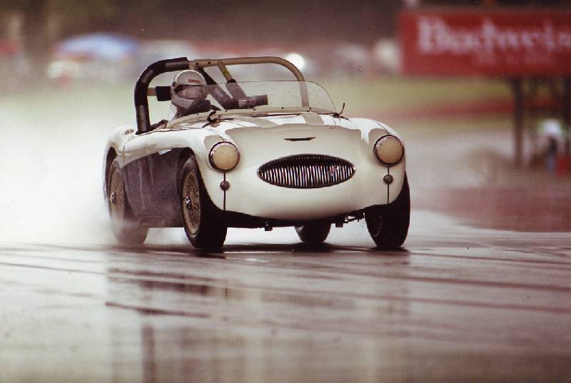
I had a reasonably good first season with the S until things went pear shaped when the crankshaft broke during practice at Shannonville, Ontario. Fortunately that track is only 2 hours from my shop so we managed to get the car back there, pull the gearbox, back plate, pan and timing chain cover and fit a replacement crank in time to get back for racing the next day.
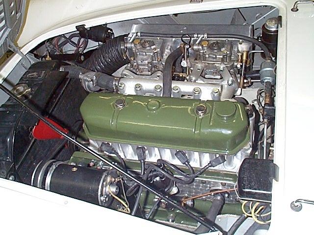
The 100S engine block, in fact the whole engine is somewhat different from that fitted to the standard Austin Healey 100. The most obvious difference of course is the cylinder head which has the ports on the opposite side of the engine so that their size is not restricted as a result of having to squeeze between the push rod tubes. This change, in of itself, may not seem to be too much of a problem until one realizes that to achieve this the head studs all have to be repositioned for the different head. Because of this the 100S block is the hardest part of the engine to replace and is therefore very valuable.
I had been very lucky in that my original block had not been damaged as a result of the crank failure and decided that if I was going to race the car much more it would be much wiser to put together a special (reproduction) engine so that my original could be preserved.
In the late 1980s, I had visited John Chatham in Bristol England who had very fast 100 which he was good enough to let me drive. This was an awesome car with the sort of power that I wanted my new engine to produce. The secret of Johns engine was the short stroke nitrided crankshaft which was from an Austin Diesel FX3 Taxi. John had cheated a little to produce his engine and had essentially used a taxi block, with its crank, and fitted an aluminium 100 head, special rods and pistions, with all the other necessary bits to make it work. This arrangement worked well but the taxi block with provision for 25 head studs, massive injector pump housing, a huge front cover to accommodate the triple row injector pump chain drive and no provision for a distributor, was not ideal for the job. John had made up an adaptor and fitted his distributor where the injector pump was normally fitted on the diesel engine but the whole thing looked very different from a 100 engine and was quite heavy but the taxi crank idea struck me as a very good one.
Over the next few years I planned my 100R engine and
worked away at collecting up parts for it. My intention was to produce
a higher revving engine more suitable for track work and it was to include
the following:
1. Taxi crank with a 4 stroke (rather than the original
4.375)
2. Lightweight forged pistons
3. Carrillo connecting rods
4. Big valves and gas flowed 100S head
5. Cam with 300 degree duration and 0.500 valve lift
6. Lightweight flywheel
7. Crank triggered electronic ignition
8. 2 x 45DCOE Weber carburetors
9. Adjustable cam timing
10. 10.5 / 1 compression
11. Strapped center main bearing
12. Gear reduction starter
I figured, in blissful ignorance, that an engine with these specs should wind up to 7000 r.p.m. and develop over 200 BHP.
I was lucky enough to have a spare head, exhaust manifold,
and a one off intake manifold for the Webers which have different mounding
stud configurations than the DCO3 Webers available from the factory as
an option for the 100S. I could modify a standard 100 block and I managed
to buy 2 NOS FX3 taxi crankshafts, with bearings on EBay!!
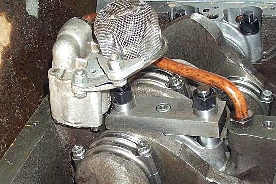
Other items such as the modified rocker cover, flat plate
tappet cover, special distributor and tachometer drive, and enlarged oil
pan were relatively easily copied from the ones in the original engine.
I was prompted into finishing the engine when I decided to take AHS3903 into the 2002 Targa Newfoundland but the rules for the Targa necessitated the elimination of the crank triggered ignition.
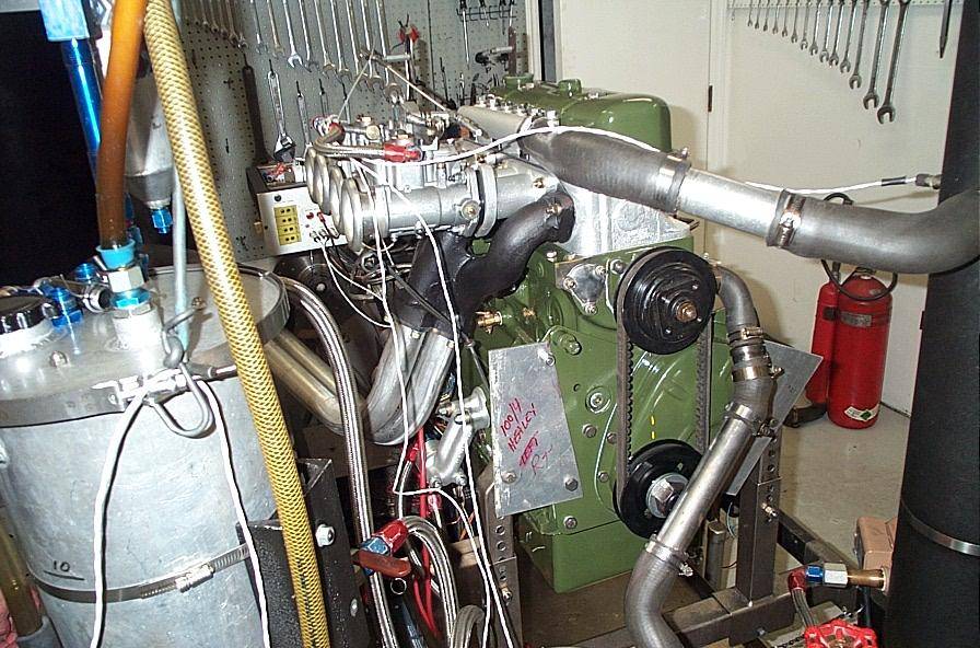
When time came to do the necessary machining and assemble all the parts I was simply too busy to take it on, so I sent the whole lot down to Barry Sale of PHP Racengines in Chicago and asked him to see what he could achieve.
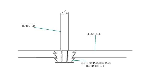
The biggest issue was repositioning the head studs in a standard 100 block to take the 100S head. The problem is that inside a block the manufacturer casts special bosses which are drilled and tapped to accommodate the head studs. In cross section the deck looks like this.
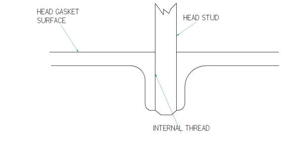
Of course if you decide that you have to move the studs
there are no bosses in the new positions so you end up with either very
shallow threads, or worse yet, trying to cut a thread where one side is
into a boss and the other is not.
In addition to this head stud issue Barry encountered a problem with fitting the Diesel crank into the 100 block. The problem was that the thrust faces on the center main bearing of the taxi crank were closer together than they are on a standard 100 crank. This required some fairly unusual machining of the block and the narrowing of the center main bearing shells.
The other problems were not too difficult to resolve. The taxi crank has 6 flywheel mounting bolts so I had an aluminium flywheel made with the appropriate mounting holes and the ring gear installed to it with the lead in of the teeth on the front side to accommodate the reduction gear starter.
I decided to stick with an original 100S type exhaust manifold after reading of the problems that the factory team had encountered at Sebring when their tube type headers broke up during the race.
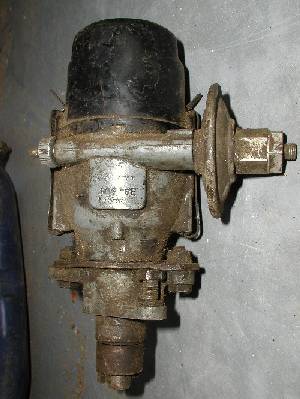
One other issue that I encountered was coming up with a suitable distributor. On the 100S engine the distributor was moved to the opposite side of the engine so that it was not under the repositioned manifolds. This move resulted in the need for a distributor which rotated in the opposite direction and I managed to get one from a 1953 Humber Hawk which fit the bill perfectly.
We consulted Dema Elgin of Elgin Cams and he recommended, and supplied, a milder cam than I had envisioned with a 274 degree duration and lift at the cam of 0.295 (0.486 valve). The rocker ratio on the 100S head is 1.65/1.
I have to give Barry credit; once he gor started he managed to make things work and to get the engine assembled and running in very short order for me to take it back to Toronto and install it before the 2002 Targa Newfoundland.
Upon completion dynamometer tests indicated that the engine was producing 166 BHP at the flywheel at 5000 r.p.m. certainly far below my expectations, but the torque was 191 lb. ft. which was a considerable improvement from the original 132 BPH and 168 ft. lb. of torque
In Newfoundland the engine performed flawlessly until we encountered a Volvo P1800 strategically positioned across the road which ended the rally for us.
After that event I, in my infinite wisdom, decided I could get more power out of the engine with a wilder cam and some careful manipulation of the specs.
The first thing I did was measure everything carefully to determine where things stood. I found that the compression ratio was only 9.22/1 and that the variation in the combustion chamber capacities was far greater than was desirable.
After pulling out a couple of the studs while torquing down the head I decided that this had to be solved once and for all.
I mounted the block in mill and bored out all the troublesome head stud threads and installed cast iron taper thread plugs. I then milled these flat and then tapped and drilled them for the studs.
I ordered up a 300 degree cam with slightly more lift, took an additional 0.050 off the head to bring the compression ratio closer to 10.5/1 and balanced the combustion chamber volumes. After careful reassembly I hauled the engine back to Chicago to have Barry test it again on his dynamometer.
We performed 22 runs on the dynamometer while Barry fine tuned the carburetors and adjusted the cam and ignition timing to get the best he could out of my improvements.
The result was an increase of only 9 BHP to 175 at a higher
r.p.m. but no improvement in torque and it was only after mulling this
rather disappointing result for some time and reading a lot more about
engine development that I realized that it was going to be very unlikely
that I would ever get much more power from this engine configuration and
here is why.
To develop power an engine has to ingest a gulp of air
(which contains a bit of fuel). The force to get this air into the combustion
chamber comes from the good old 15 p.s.i. (pounds per square inch) of atmospheric
pressure. What the atmosphere has to do, when the inlet valve opens, is
accelerate a slug of air through the port, past the valve and into the
cylinder. The problem is that although that slug of air doesnt weigh that
much 15 p.s.i isnt that much of a force. The laws of physics determine
that the rate of acceleration is proportional to the inverse of the mass
being accelerated and the force accelerating it. In simple terms the old
atmospheric pressure can only push so much air down that port in a given
amount of time. At 6000 r.p.m. the piston moves from the top, essentially
where this process begins, to the bottom, where it ends in 1/100th of a
second. That isnt that long. Now there are a bunch of mitigating circumstances
but when you get right down to it that is what has to happen. Things can
be improved a bit by making the valves open longer and further, or cleaning
out the ports and fitting bigger carburetor throats but the fact remains
that 10,000 r.p.m. just wasnt going to happen on a long stroke 2500c.c
engine.
This concept is summarized in the old adage that it is
very hard to exceed 3000 - 3500 ft/min mean piston speed and with its 4
stroke the 100R engine is doing 3333 ft/min at 5000 r.p.m. Of course
F1 engines were getting upwards of 5500 ft/min in the early 90s but thats
a very different story.
Mike Salter
Precision Sportscar