Hunter Twin Overhead Cam Head Drawings.
by
Larry Varley


The following is an overview of 27 drawings, most of which are signed by Harold Hunter describing his twin overhead cam conversion for the Austin Healey 100. None of the drawings include a title block describing part number, revision date, material of construction etc. usually found on engineering drawings, in fact only one drawing is dated (May 23rd 1955). This makes the task of allocating order to the design process quite difficult as many of the drawings appear to be "thinking on paper" and involve variations in design detail of the same components. The drawings do not fully describe the prototypes that can be seen under Hunter Head Images on my index page, this comes as no great surprise as low budget development work quite often involves the make it now and draw it later principle. In fact to quote Geoffrey Healey discussing the development of the Healey 100 from his book The Healey Story "many of the parts were made by Roger (Menadue) without drawings and were then drawn". While some drawings deal with machining of components, the drawings that deal with the castings appear to have been produced to provide the necessary information to produce the patterns. Only basic machining dimensions are shown and tolerances are rare. Hunter described the four heads produced as prototypes, and looking at the drawings it becomes clear that only enough was done to make it run. Having spent the last thirty years involved in engineering, through manufacturing, foundries, design and prototype construction, in my opinion, (others may disagree) what Hunter produced was a successful design, ready to be fine tuned into a production model. It is unfortunate that this didn't happen considering the  time, effort and expense that must have gone into producing the prototypes, and a shame that his work was left to judged by them.
As part of my ongoing interest in the Hunter design I intend to faithfully reproduce the drawings in digital format (autocad) as time permits.

Valve Gear
The drawings describe a twin overhead cam cylinder head and cam drive arrangement to suit the Austin Healey 100 engine. The design incorporates a 60 degree included angle between the cam boxes which are cast integral with the head. The valve gear arrangement is similar to that seen on Jaguar engines of the period, having an adjustment shim sitting directly on top of the valve stem. The shim in turn sits beneath a tappet which in turn sits directly below the cam (see image).


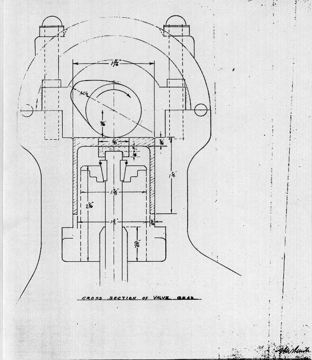
These tappets appear to be running directly in the head. However many aspects of the design are not shown in the drawings including the camshaft bearings ( if there were any ) so it is dangerous to make too many assumptions! It should also be noted that materials of construction are rarely mentioned an exception being one of two camshaft drawings which calls for "Atlas SPS245".

Camshaft Drive

The two overhead cam shafts are driven by the existing camshaft via two duplex chains of 3/8 pitch. The first runs on a 23 tooth sprocket (Healey crank sprocket) attached to the existing cam and sprocket by an adapter. In some of the arrangement drawings there appears to be a fairly crude attempt at incorporating a timing adjustment in the adapter design by means of tapered seats for the sprockets.  I should mention here that the drawings depict 5 variations in this primary drive and chain cover arrangement between the existing cam and overhead inlet cam. The variations mainly involve the chain cover design, either a single cover over the chain from the existing cam to the overhead inlet cam or the two piece design seen in the photo's, the latter probably to allow for changes in either head height or variations in the block height. Many of these drive and cover variation drawings are only partly dimensioned, perhaps indicating my thinking on paper scenario.  In some drawings the exhaust cam is shown extended through the front chain cover and fitted with a pulley to drive the water pump and generator. In these designs the crankshaft fan belt pulley is removed with the cast timing chain cover blanked off over the end of the crankshaft. None of the drawings show the adapter for the distributor drive off the exhaust cam as seen in the photo's of the head. Some drawings also show the cams supported in bushes in the front chain cover. Two 23 tooth sprockets are fitted to the front of the overhead inlet cam, the front sprocket being the primary drive from the existing cam, the rear driving the exhaust cam also fitted with a 23 tooth sprocket. Other than the rubber ring tensioner fitted to the existing cam sprocket, no means of dealing with adjustment of the two additional chains is described or it appears allowed for.
Cylinder Head
The combustion chambers are of hemispherical design at 1 15/16 radius from a point 7/8 below the head gasket face, giving a diameter at the gasket face of 3 7/16 inches. The distance from the cylinder head gasket face to the centre of the cams is 6 1/8 inches. The spark plug holes are shown in one drawing at 10 degrees angle toward the front of the head and at 15 degrees in another. It appears that 3/4 inch reach plugs were allowed for.  While the valves are shown at the centre of the combustion chambers the spark plugs are toward the front. Four inlet ports are shown on the left side of the head at 1 1/2 diameter at both the manifold face and valve seat. The inlet ports sweep toward the rear of the head from the manifold face. There are also four exhaust ports on the right side at 1 3/4 diameter at the manifold face and 1 7/16 diameter at the valve seat. The exhaust ports are at ninety degrees from the centre line of the head.  Valve seats are shown cast in place, with the head material surrounding the seats on three sides. While the design is based on the 100/4 head stud pattern, one extra stud has been added between cylinders two and three 2 5/16 inches from the centre line of the cylinders on the inlet (left) side. This stud emerges through the top of the head between the cam boxes as do all the right hand side studs, whereas the rest of the left hand side studs emerge in small cutouts between the inlet ports low in the side of the head. Oil supply to the valve gear is shown as a hole emerging in the bottom of one cam box, how this supply is directed to the cam bearings is not shown. A 1 inch oil return hole is shown in the front of the head for oil to return to the sump through the chain cover system. Water return is also shown as a 1 inch hole in the front of the head. The location of both these holes varies in the two versions of the cylinder head drawings.
Camshafts
There are two drawings detailing two versions of the camshafts. Both drawings depict the camshafts as have three bearing journals of 1 1/4 diameter and a 1 1/2 diameter shoulder each side of the centre journal to deal with end float. While cam lift is specified on both drawings, duration is not specified.
In one drawing the cam lobes are shown at 5/8 wide with a lift of .406 inches. No centre hole is shown for lubrication and material is not shown. The exhaust cam is extended through the front cover in this version.
The other camshaft drawing shows the exhaust cam dimensioned to accept only the sprocket, and as such does not fit with any of the designs or the photos of the head produced. In this drawing the cam lobes are shown as 3/4 wide, with a lift of .3805 inches. A 3/8 diameter centre hole is shown with cross drilling for bearing lubrication, and a 1/32 hole in the heal of each cam lobe, to direct oil to the tappets. Material is listed on this drawing as "Atlas SPS245".
Pistons
The pistons are shown as domed with an overall height of 2 1/4 inches from the centre of the 7/8 diameter gudgeon pin to the top of the crown. The dome is shown as 1/4 inches high. Piston diameter is 3 7/16 inches and piston length is 3 9/16 excluding the dome. Dimensions are given for three piston rings.


In closing I would like to that the friends that have provided information on Hunter and helped me to assemble the information that I have so far.
 

 Back to Austin Healey 100 Restoration Site