Resistance welding plays a most important part in the body building industry and a prominent feature of any mass production plant is the lines of more or less elaborate automatic welding machines which unite numerous sheet steel panels and sub assemblies into the typical unit construction body shell. Other modern welding methods, however, are likely to be more applicable where the scale of operations does not justify the installation of expensive and complex tooling.
Small-scale production
It is not only the cost of the plant and equipment
that prevents large resistance welding machines from being used in relatively
small scale production. Matched press tools for body panels are so
costly that enormous production runs are required to amortise them.
Hand panel beating, therefore, is employed for small quantities, while
rubber press tools, requiring only a shaped male die instead of an intimately
matched pair of tools, can cope economically with intermediate quantities.
Light alloys, on account of their ductility and ease of working, are widely
used in conjunction with these forming methods. Furthermore, with
the class of car commonly built in such limited numbers, weight saving
is often of some importance.
Resistance welding is unsuitable for use on aluminium alloys, and an attractive alternative is inert gas shielded arc welding. This method is being increasingly employed in plants concerned with the production of specialist and high performance cars, and also for goods and passenger vehicle bodywork. Apart from the main advantage of the process, the prevention of oxidation of the heated metal, it provides clean, smooth and strong welds and has an easily controlled underbead. These are useful features where finish is important, as it is in these sections of the motor industry.
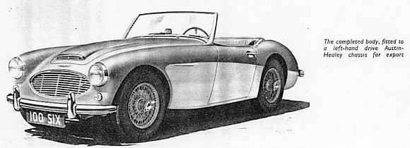
A good example of the class of car to which
the above considerations apply is the Austin-Healey sports model.
While this car is a popular representative of its type, it is designed
for a relatively limited public and cannot be produced in anything approaching
the numbers usual for the typical family saloon. The body shell is
composite steel and light alloy structure, manufactured at West Bromwich
by Jensen Motors Ltd. This firm has a long connection with specialist
car production, and has acquired wide experience in the production methods
economically applicable to limited outputs.
To provide the stiffness essential for stability at high speeds, the chassis frame is a fabricated steel structure of great depth, additional strength being provided by the body side panels which are also of steel. The remainder of the shell, comprising front and rear ends and top decking, is generally of 16 S.W.G. aluminium-manganese alloy to B.S. 1470 N.S.3. This combination of materials results in a very favourable overall strength:weight ratio.
Extensive use of aluminium
In the complete body, the light alloy structure
comprises two large one piece sections, forming respectively the whole
of the upper surfaces before and behind the cockpit. To simplify
assembly and tooling, each main panel is built up by welding together a
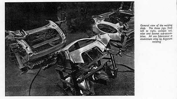
number of smaller sections,. The general view of the welding shop
shows the breakdown of sub-assemblies quite clearly. In the foreground
the nose-shell section, comprising four small and simple pressings, is
mounted on a jig. At the left, a complete tail section, built up
from seven separate parts, is ready to be removed from its jig. At
the right, the nose-shell section is about to be welded to the bonnet-top
structure, which is itself made up from three sections.
This method of assembly reduces both the size
and the complexity of the formed parts, most of which receive their basic
shaping in a rubber-platen press. Re-entrants, flanges and small
cut-outs are formed by hand panel-beating in special jigs, Extremely
accurate jigging is called for to obtain the required accuracy, and a high
standard of welding is demanded to ensure that the panel joints are invisible.
That these aims are attained is evidenced by the excellent finish of the
completed body.
Probably the most important factor affecting appearance is the choice of Argonarc welding for all the panel joints. The advantages of this method from the point of view of protection of the light alloy material from oxidation is well established. What is equally important in this application is the very small amount of distortion which results from the cooling effect of the argon gas shroud, and the speed with which welding can be effected. Much thought has been given to the design of the jigs to clamp the panels firmly in alignment, to maintain the correct spacing between the joint faces, and to control the welding underbead.
Welding jigs
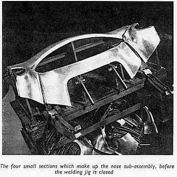
The jig for the nose assembly, with the individual
panels in place, is illustrated. The clamps, which are specially
shaped to form welding guides, can be seen in the open position.
When they are closed, they automatically position the panels to leave a
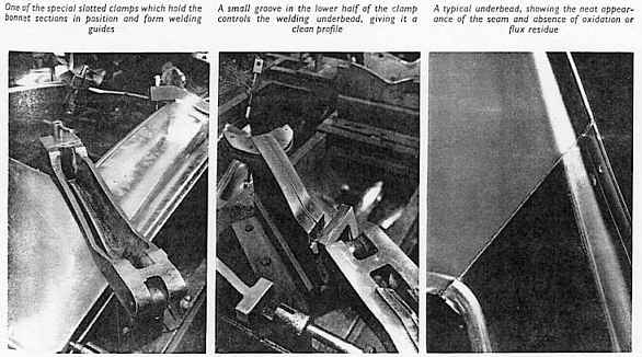
maximum weld gap of 1/16 in. One of these clamps in the open position
is shown in detail, this time as part of the jig for the bonnet top assembly.
The upper half of the clamp is slotted along the centre line, giving access
to the upper surface of the panels for a width of about ¼ in on
each side of the joint line. The sides of the slot are chamfered
to provide easy access for the welding torch. Penetration is controlled
by a semi-circular groove formed in the lower, fixed half of the clamp.
This ensures a net underbead, about 3/16 in wide and 1/8 in deep.
Since all the proud metal on the outer, visible surface of the panel is
ground away to provide a smooth finish, the underbead forms a reinforcement
to the joint. The clean appearance of the underside is well shown
in the view of the reverse side of a joint in the bonnet top panel.
No post-welding treatment of any kind is required.
This illustration also gives some idea of
the complete lack of distortion in the light-gauge material. Reference
has been made to the importance of correct alignment of the sub-assemblies.
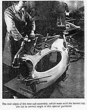
One of the ways in which this attained is shown in application to a completed
nose section, subsequent to welding and smoothing down the top beads.
Before it is mated to the bonnet top panels, the upper rear edges must
be carefully shaped to the correct angle. This operation is carried
out in a simple trimming jig. The nose section is clamped in a fixture,
resembling the welding jig in which it was assembled, and two large shear
blades are brought down on the rear edges to cut a clean, accurately positioned
face ready for welding. In the same fixture, the two levers at the
front are manually operated to punch a hole in the flange at each side
of the panel for its eventual attachment to the chassis structure.
The final stage in the fabrication of the large front panel consists of
welding the nose section to the bonnet top section in a large jig built
on similar principles to the others. Welds are then ground down and
the seams are smoothed by hand tools, as shown in the illustration of an
operator finishing one of the longer welds between the two parts.
Electrical equipment
There are several points of interest in the welding technique and in the equipment used, which is of the latest type manufactured by the British Oxygen Co. Ltd. As is usual in the Argonarc welding of aluminium alloys, alternating current is employed. The reason is that the electrode-negative direct current, which gives efficient heat transfer to the work, the well known scavenging effect on the refractory oxide film is absent. Electrode-positive direct current, on the other hand, while providing the necessary oxide removal function, concentrates most of the arc heat at the tip of the tungsten electrode. With the high thermal conductivity of aluminium, this results in shallow penetration and low speed, as well as introducing the danger of contamination from the molten electrode tip.
Current is supplied to each pair of torches
by a Quasi-Arc ACP 2 300 transformer welding set, which can supply 300
A simultaneously to each torch. High frequency units are inserted
in each circuit to provide instantaneous re-iginition of the arc at the
zero point in each half cycle, and to ensure automatic initial ignition
without contact between electrode and work. This device consists
essentially of a spark-gap oscillator which superimposes a train of high
frequency oscillatory voltages on the main 50 c s supply, phased to milliseconds,
sufficient to re-establish the art without the need for an excessively
high arc voltage.
Inherent rectification of the welding supply
in the arc, which gives rise to an undesirable D.C. component, is countered
by including in the circuit a D.C. suppressor unit, consisting of a bank
of series capacitors which effectively block the direct current.
By ensuring that the electrode-positive half-cycle will be as long as the
electrode-negative, efficient scavenging of the refractory film is ensured.
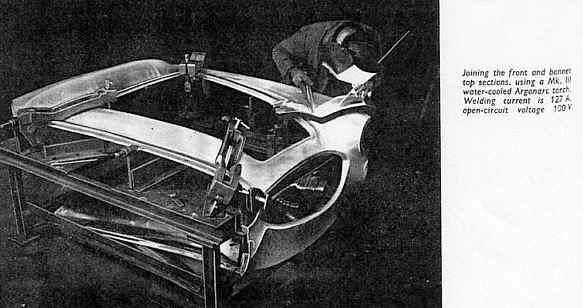
The illustration of the welding operation uniting the nose and bonnet-top sections shows the typically oblique angle at which the 1/8 in. Alda pure aluminium filler rod is held at the leading edge of the advancing weld pool. The torches are of the Mk 111 water-cooled type, water and argon flows being controlled through an economizer unit on a bench. When the torch is not in use, it is hung on a small hook which automatically closes both the argon and the water valves. The open-circuit voltage is 100V, and each torch takes 127 A, under which conditions the average welding speed is about 10in. min. There is a total of about 13ft of welding in each complete set of panels. The average weekly output of complete units is about 125, which represents a very creditable figure when the time required for handling is taken into account. Argon is fed at 12 to 16 cubic ft per hour, the consumption being very modest at 300 cubic ft per week, or just over 2 cubic ft per body.
Finishing details
One interesting point in connection with the
assembly is that, on some of the panels, flanges round openings must be
hammered flat over a short distance to allow the part to lie evenly in
the jig. It is not possible to weld right to the end of the
joint because the clamp is in the way. In such cases, the joint is
completed after removal from the jig, using an ordinary oxy-acetylene torch,
aluminium filler rod and Alotectic flux. The extra heat from the
use of the flame has been found to have a useful annealing effect which
eases the subsequent operation of restoring the flange to its original
contour by panel-beating.
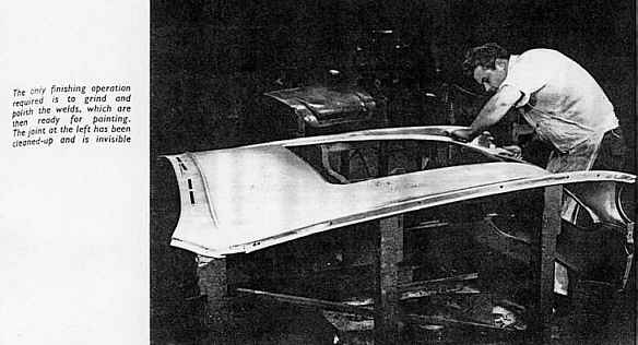
When the two main panels are completely assembled,
they are prepared for finishing by a skilled panel beater. Irregularities
in the panel surfaces caused by handling, or due to marks in the original
sheet, are planished out and the weld beads on the outer surfaces are ground
flush, filed, scraped and polished, as illustrated. So good is the
finish at this stage that no sign of the weld is visible, and no solder
or other filling is required before painting. The neat underbeads,
as already mentioned, are left untouched to provide a degree of reinforcement.
They have a useful incidental function in that, in the event of subsequent
accidental damage too severe to be beaten out, they delineate the exact
position for cutting out and welding in a replacement panel.
Range of torches
Although the equipment used by Jensen Motors
Ltd, for this high-class work is simple and compact enough to encourage
its use in the smaller workshop and even for repair work where aluminium
or its alloys are concerned, its capacity for heavy work is considerable.
The water-cooled Mk 111 torch can weld continuously at 300 A, or higher
for intermittent duty. For sustained operation at high currents,
a water-cooled shield is available to replace the normal ceramic argon
shield. This modification makes possible the continuous welding of
aluminium up to ½ in. thick. With the ceramic shield, the
normal limit in aluminium is 3/8 in.
For even heavier work, the Mk V torch can
handle up to 600 A, while at the opposite end of the scale there is a simple
air-cooled Mk 11a torch for welding at up to 100 A. The usefulness
of the Argonarc technique has been greatly extended by the introduction,
chiefly in response to the demands of the aircraft industry, of two miniature
models, known respectively as the swivel-headed torch and the pencil torch.
Of extremely compact design, the pencil torch is only about 5 in long,
and is held in the hand in the same manner as a pencil. The cable
is fed through the bore of the transparent argon tube, which enhances the
ease of handling. This model, and the swivel-headed version which
incorporates a head that can be adjusted through an angle of 48 deg, can
be applied and operated in the most awkward locations. Despite their
small size, they can work intermittently at 75 A. They can safely
be used on stainless steel and other metals down to 0.02 in thick, producing
neat and sound welds.