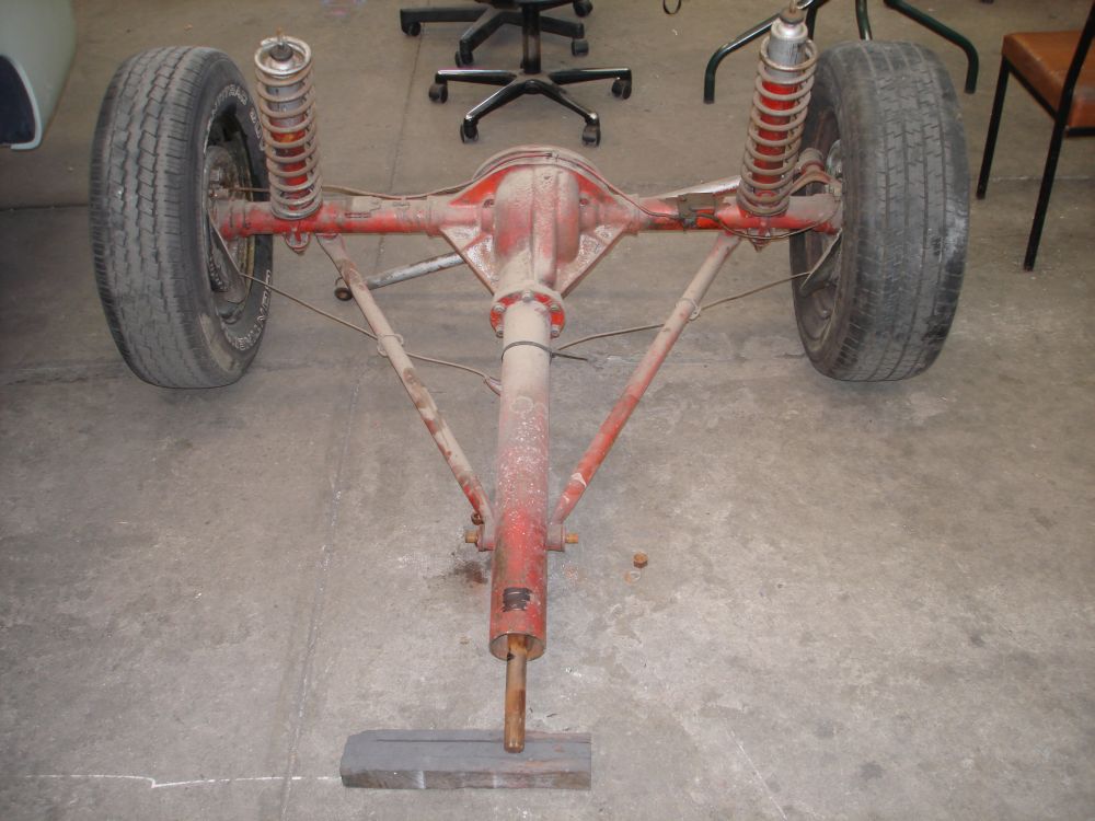
The torque tube, diff and panhard rod removed from the car with the original torque tube stabilizer cut off.
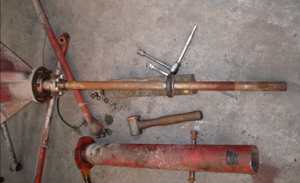
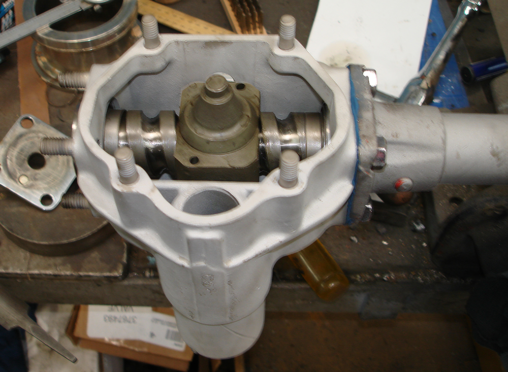
Torque tube drive shaft exposed, with centre bearing still in place. This bearing has a rubber outer casing to absorb vibration and harmonics.
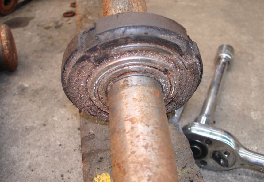
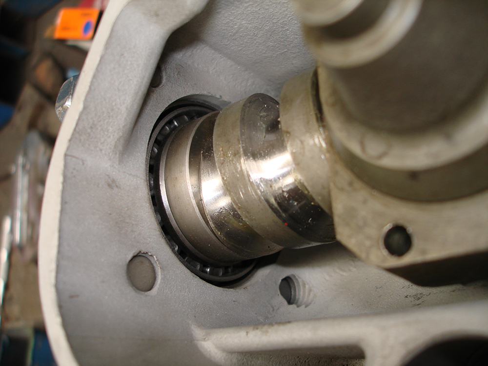
Centre bearing with wire retaining clip
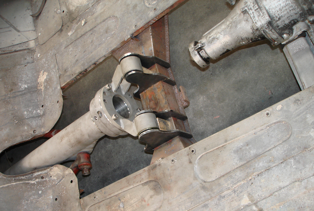
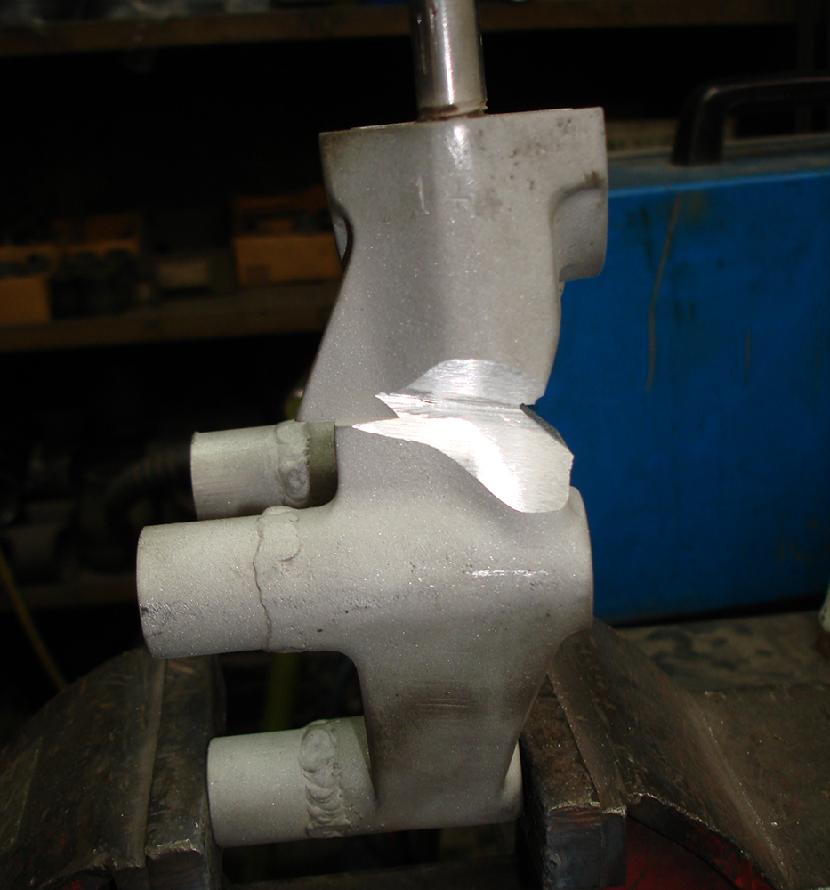
Torque tube with new double row ball race swivel joint tacked in place
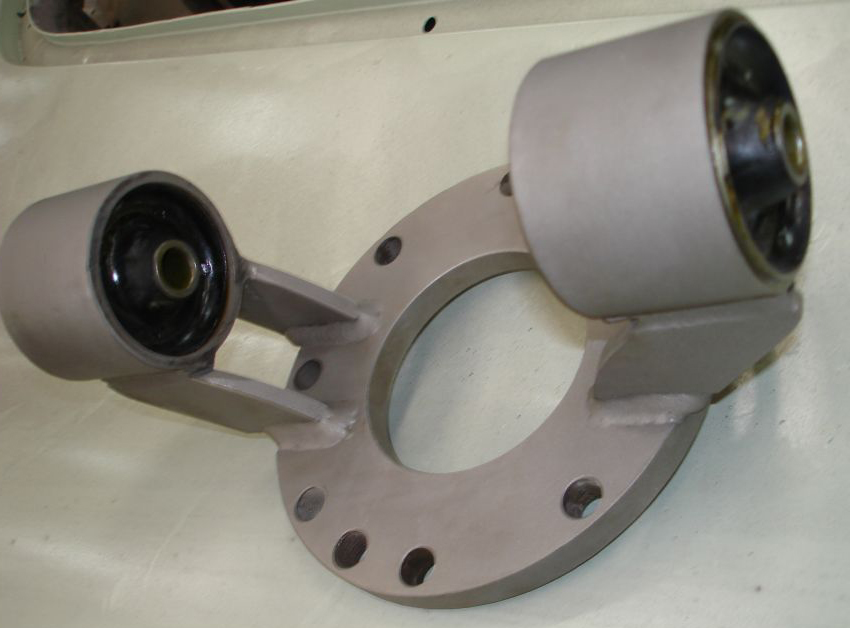
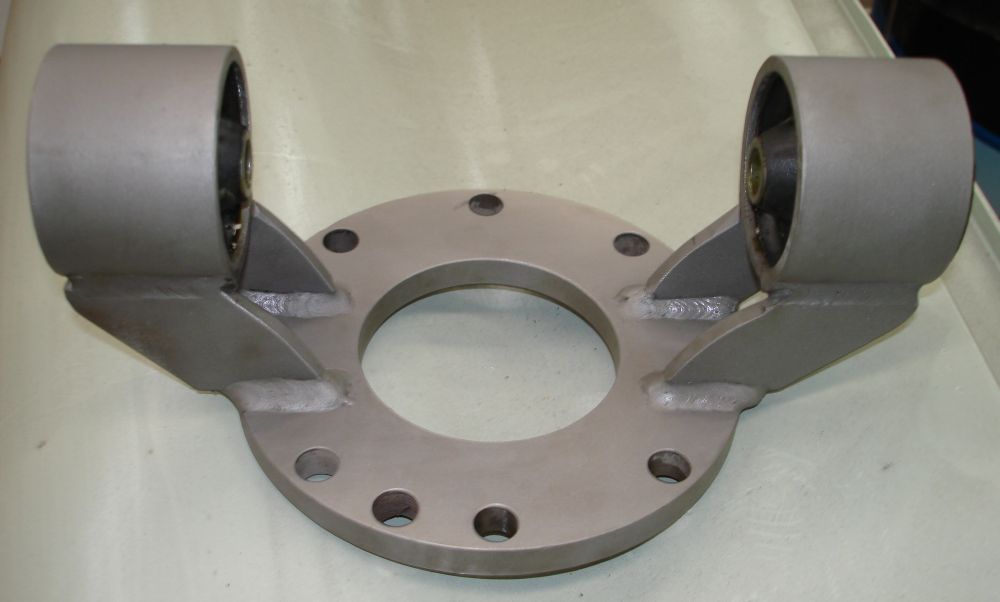
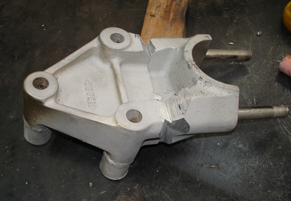
Fabricated torque tube front mount.
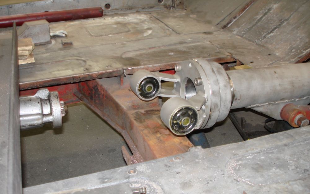
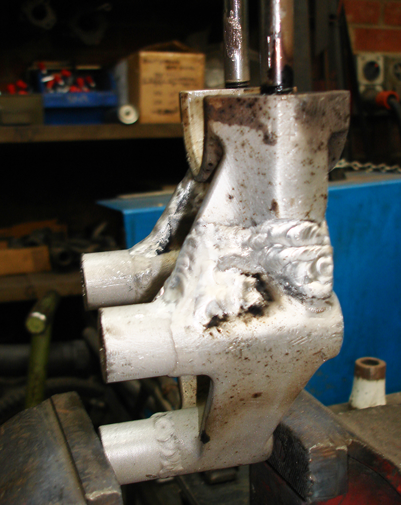
Front mount attached to swivel joint.
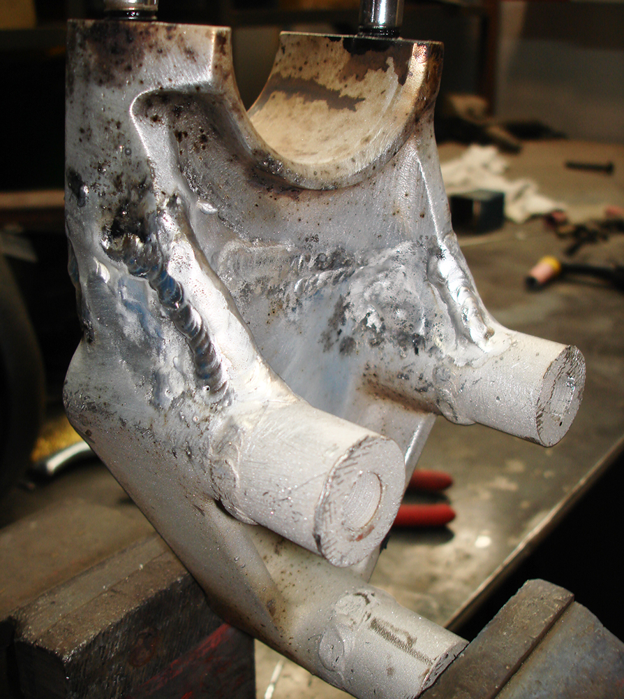
Aligning torque tube and fabricating mounts
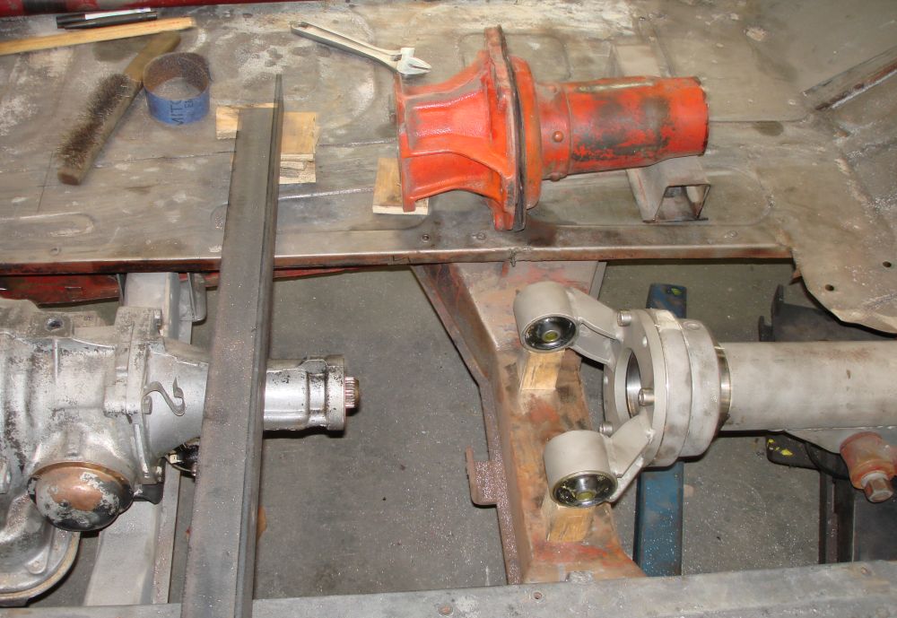
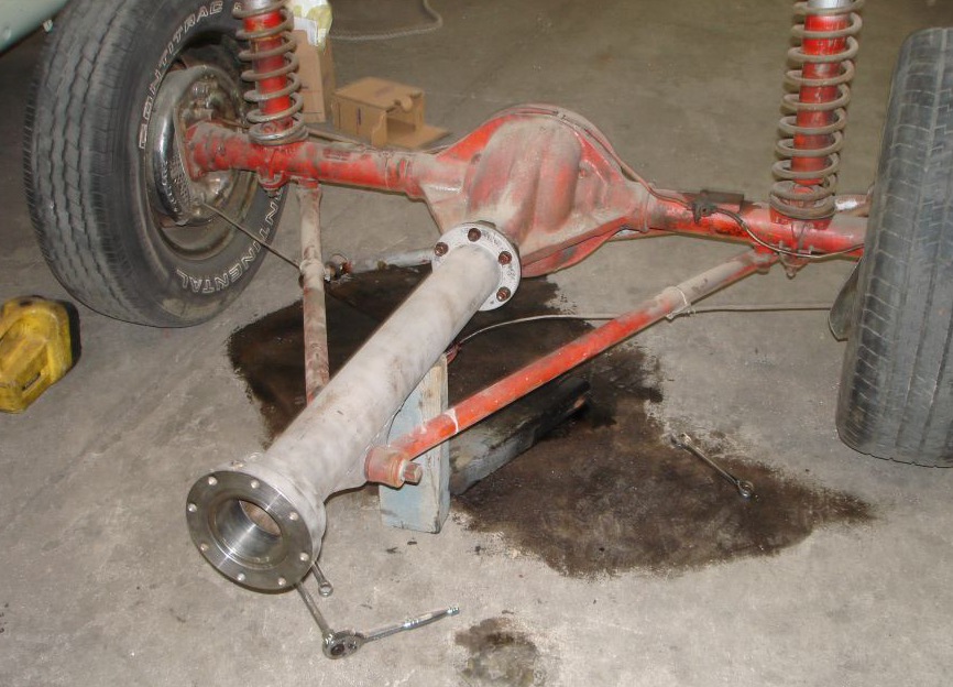
The new arrangement with the old torque tube stabilizer ( in red ) behind. It wasn't a viable proposition to use the original torque stabilizer with an aluminium gearbox, so a new design was required. I have been mindful of the fact that the Corvette 327 will be putting 300HP through the driveline.
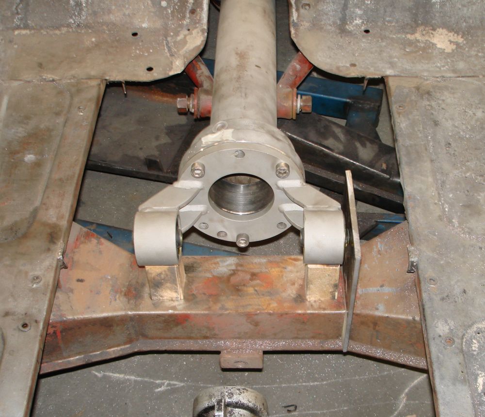
Front mounts in place waiting for the shortened drive shaft to come back from the machinist ( I really do need a milling machine ) so final alignments can be measured.
While I'm waiting for the torque tube drive shaft, I'm completing the right hand drive steering box. Fortunately the XK120 Jaguar uses the same steering box as the Nash Healey, however the worm is one less turn than the Nash unit so I hope the steering doesn't end up too heavy. The housing is reversible, so that was no problem. This is a worm and circulating ball system, with the balls housed inside the nut shown. This worm and nut was purchased from Racing Green Cars in the U.K in right hand drive format. Where the original unit has a simple V shape groove in the worm, this replacement has a full radius for greater surface contact with the balls.
At the same time I'm converting the worm bearings to tapered roller rather than the point contact balls in the original box. I used a Timken 0711 and 07210X bearing unit, and had the inner and outer race re ground to fit the housing and worm. This way keeping the worm and housing standard. Using the original worm end washers, this moves the worm forward in the housing, and a 6mm spacer was required behind the front housing cover to allow for extra length with the tapered roller bearings. The nut still travels the full length of the housing.
The steering box mounting bracket being prepared for conversion to right hand. As the chassis is tapered this bracket must be modified for right hand installation.
The bracket tig welded with new gussets for extra strength. 20mm spacers also tig welded in place to step the box further out to clear the V8 engine. The spacers were loose on the original conversion.
Another view of the modified steering box bracket
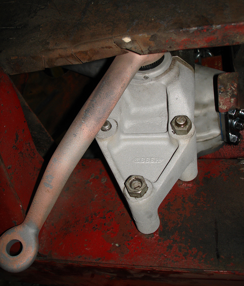
The completed bracket installed for trial fitting with the steering box
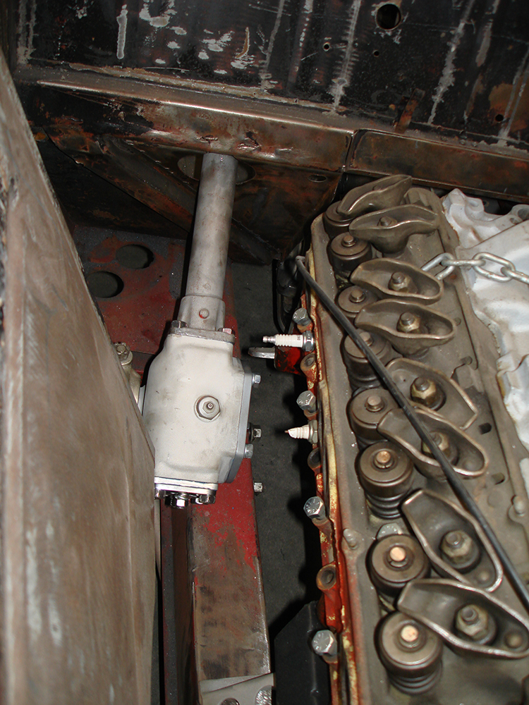
The completed steering box installed to check clearances and operation. The 6mm spacer mentioned above can be seen at the front of the steering box
Page 11
Home