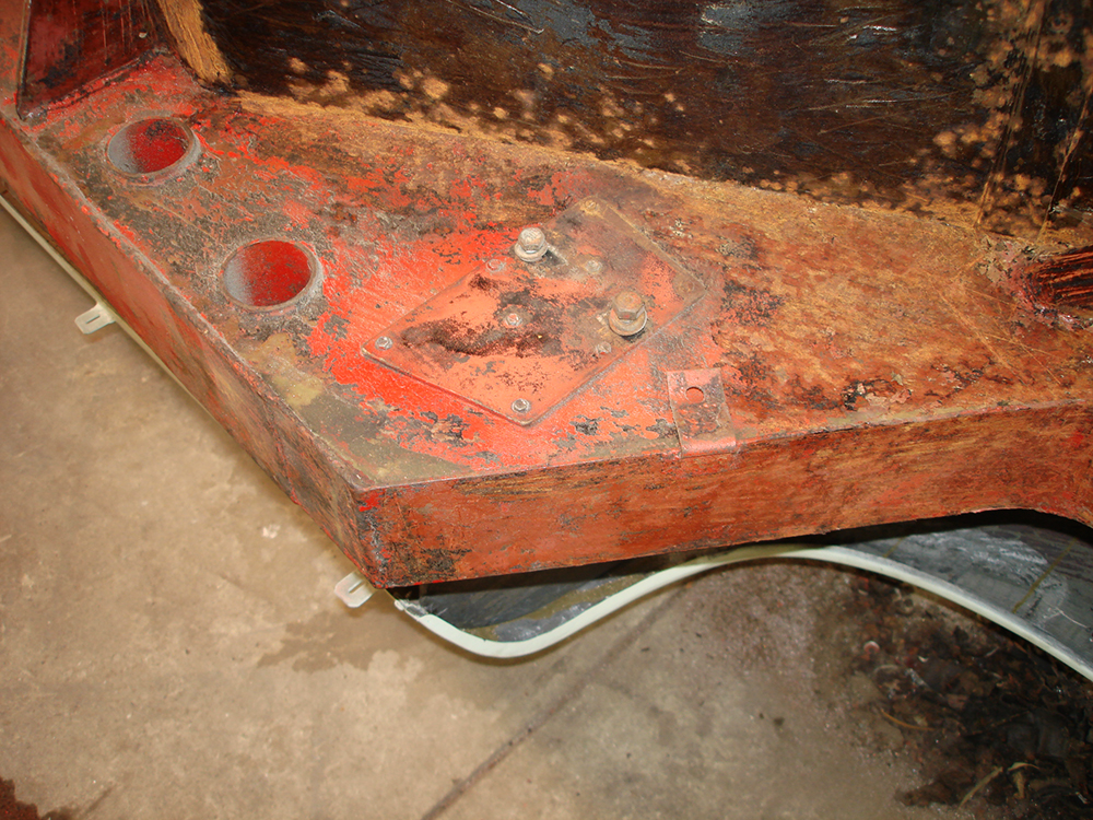
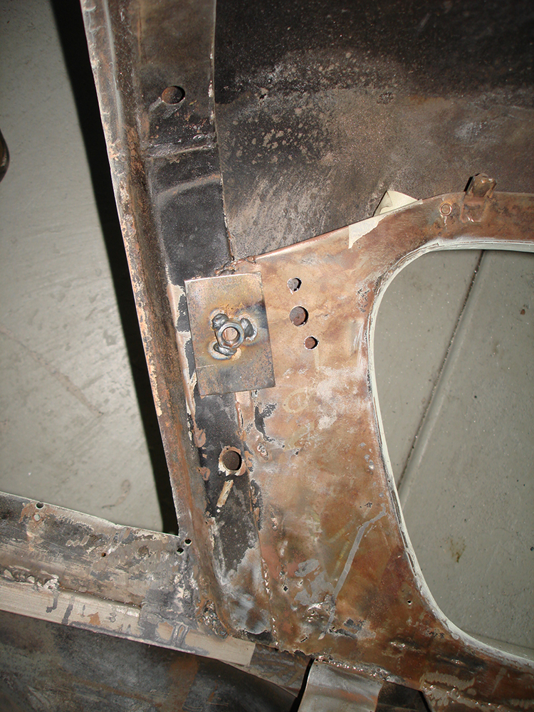
I think the plate seen above is original ?even though in the case of this car it was used to mount an electric fuel pump. I will retain it for a new high pressure pump to feed the fuel injection system that will be used on the 327 Chev engine. The engine is progressing and I will write that up in the next episode.
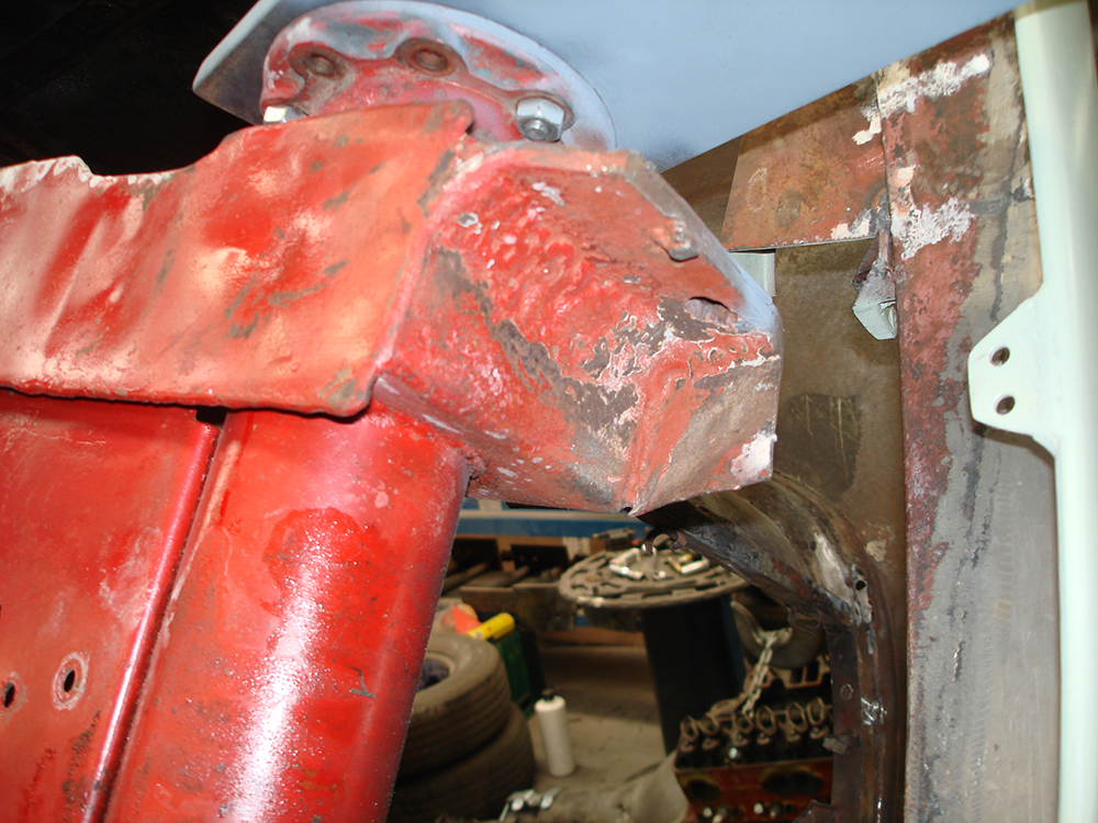
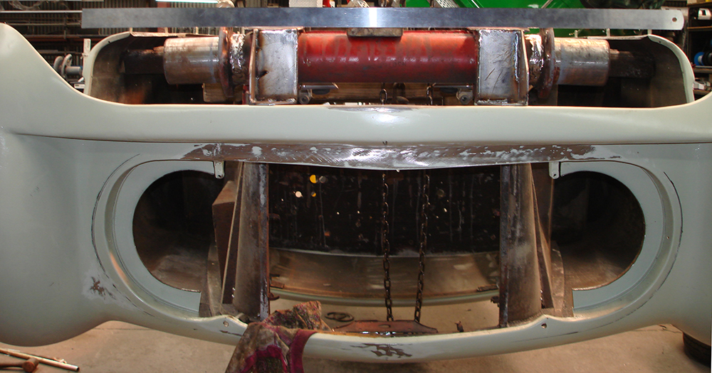
The front of the chassis where the bumper mounts has been badly repaired with a massive fillet weld, this will be rectified.
The front of the chassis cut back and ready for repairs.
Repairing the front of the rails with new steel
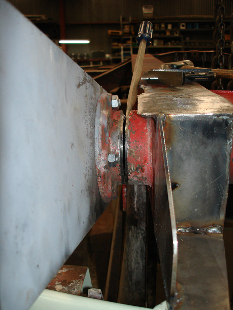
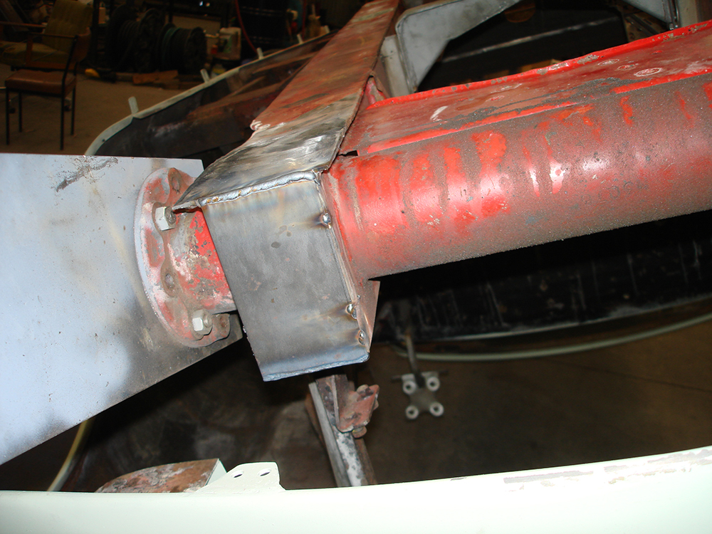
The front of the rails now repaired. I'm now adding a bit of negative camber to the front suspension to suit modern radial tyres. The only practicle way to achieve this, I believe is to change the camber by cutting the cross tube, wedginging it out and re welding. The entire suspension unit will be pushed out at the lower edge.
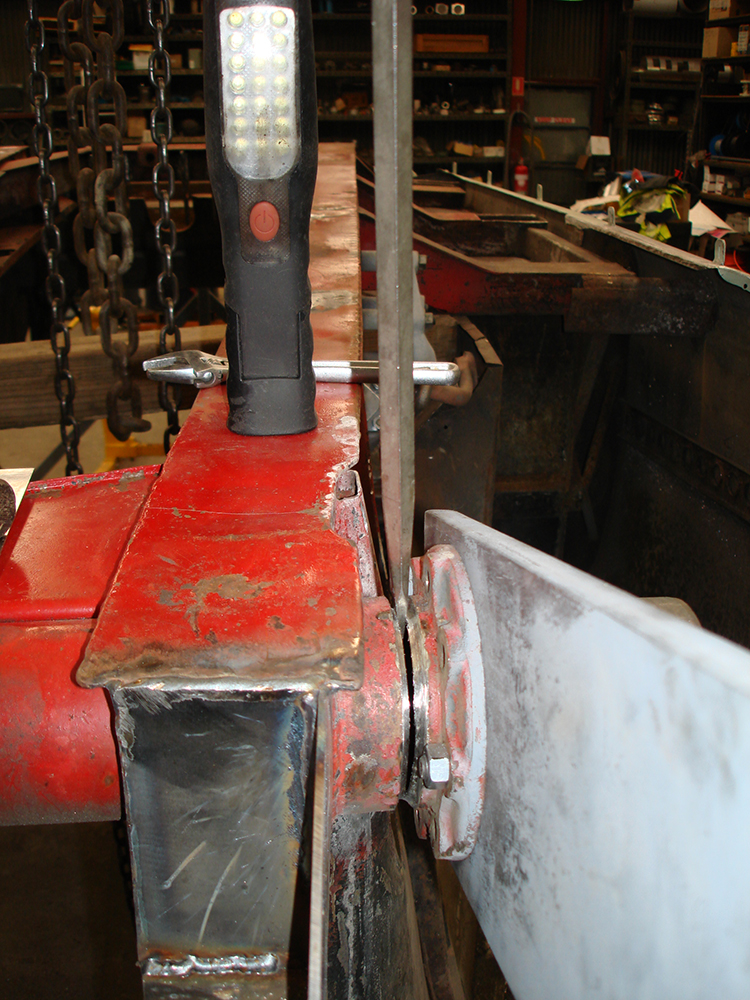
The same process on the other side wedging out the tube prior to re welding
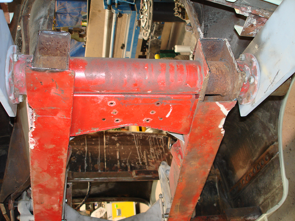
It can now be seen relative to the straight edge that both sides of the cross tube have been moved toward the top of the car to provide negative camber, and welded back to the central section of the tube.
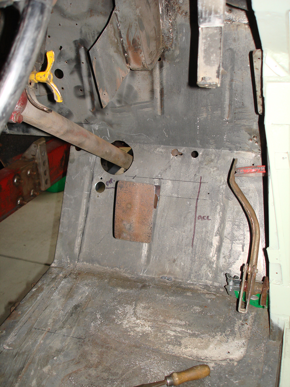
Brake booster and master cylinder assembly held in place while I work out mountings. The brake pedal arm can be seen going through a slot in the cabin floor.
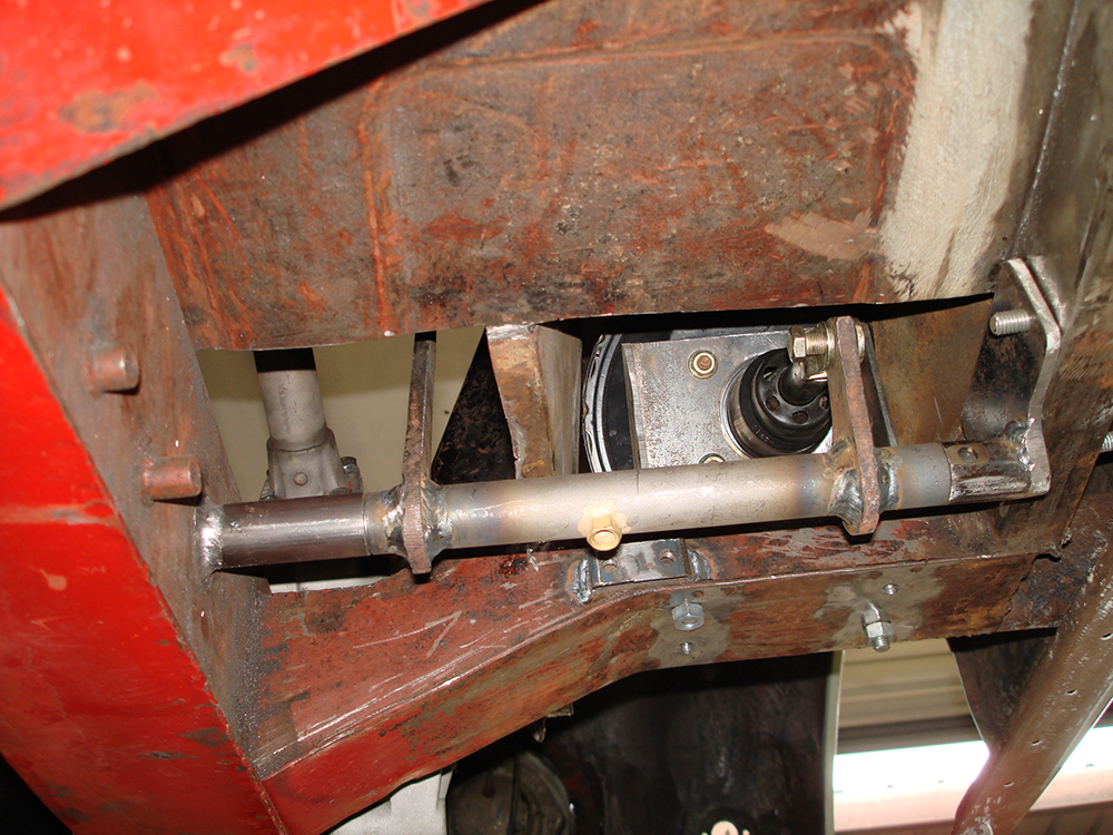
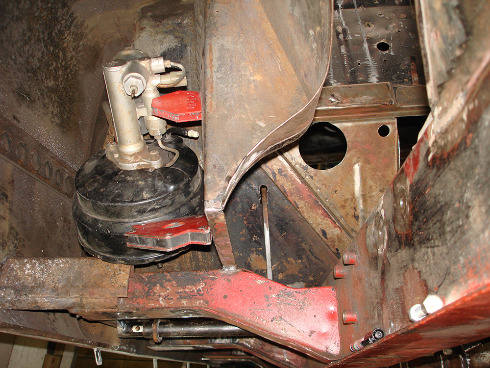
The brake booster in place, 4 crush tube through the outrigger are used to bolt the booster bracket in place. An original hole through the chassis rail is used and a tube welding on place for the cross shaft. A bracket has been fabricated to support the shaft on the right side, and once again there are crush tubes welded through the box section. Healey 100 components have been modified and used to make the system and they rotate on a 20mm stainless steel bar. A 1/8 BSP socket has been added for a grease nipple.
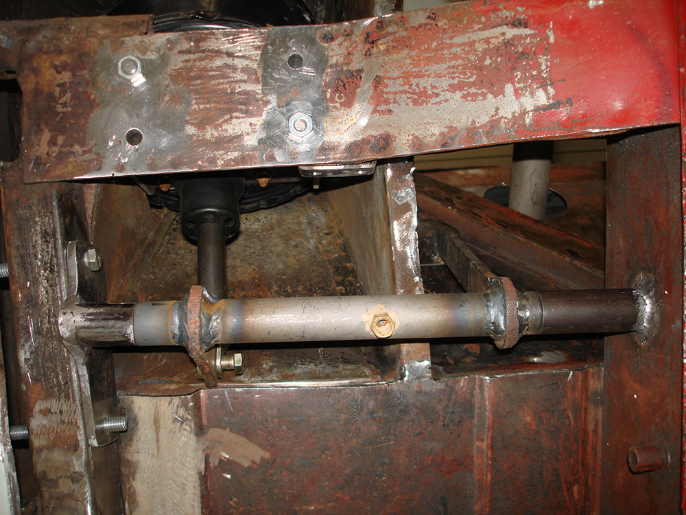
A view from below shows the completed system.
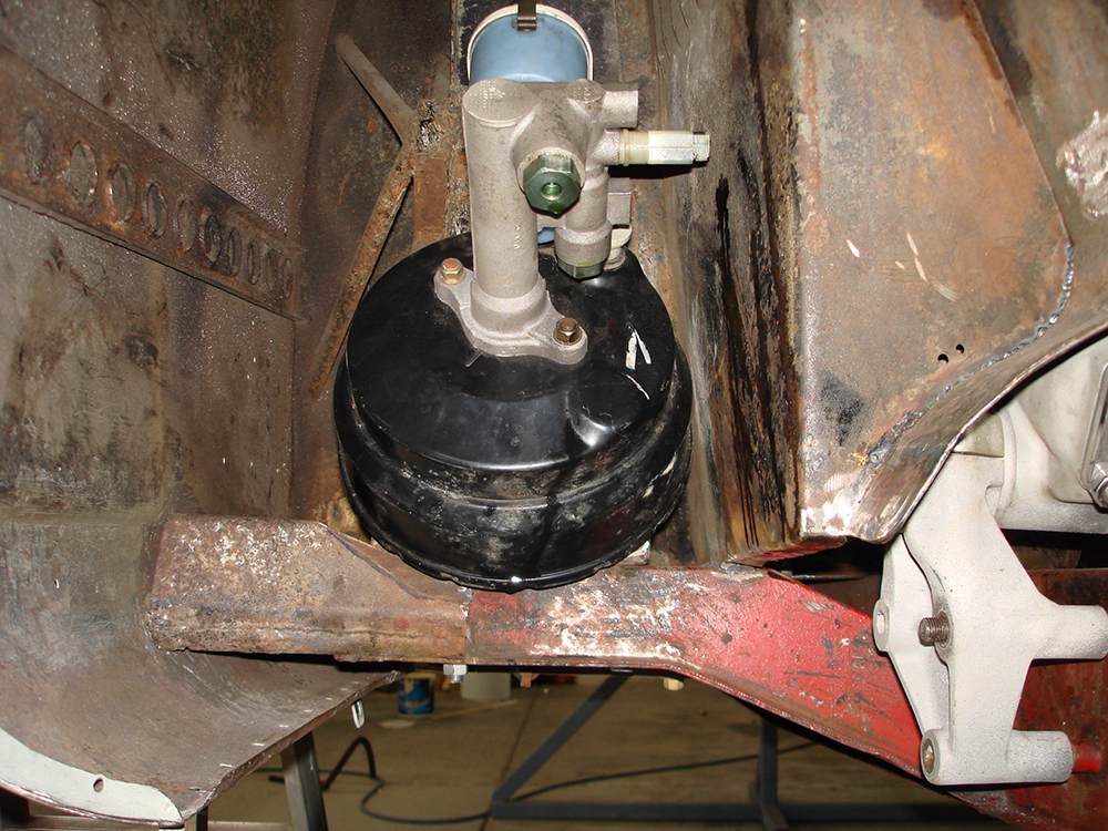
The final position of the booster which will be hidden behind the standard aluminium inner guard closing panel. On the right side of the image is the steering box mounting braket modified for right hand steering, and welds where the engine bay panel has been reprofiled to sweep around and clear the steering box.
Right hand drive brake pedal and setting up for the hand brake conversion.
Seat belt mounting plates prepared and ready to be plug welded into the pillar.
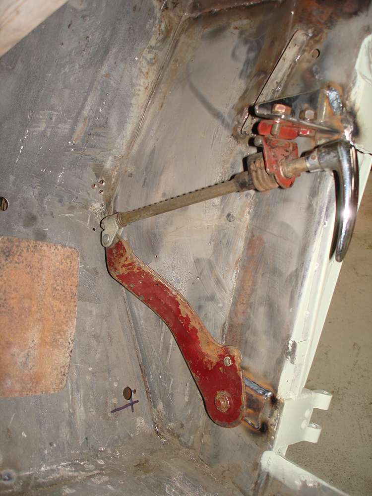
Hand brake mounting moved to the right side. The red lever will be modified later.
Making sure the trims still fit and attempting to work out how all of the interior trim that was supplied loose with the car is supposed to fit! Still working on that and I need photos of an original 53 coupe. My early 54 still has the same arrangement with wide rear shelf as the 53 model.
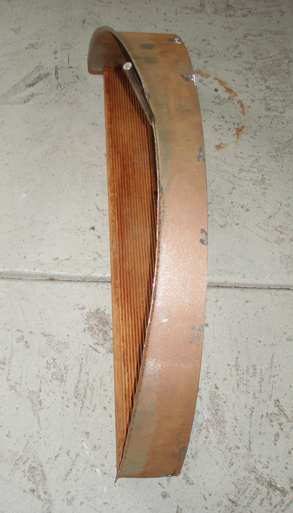
Making up the rear inner guard fillers. The rolled steel strip is secured to a board while I use a home made tool to turn up the edge to provide a flange.
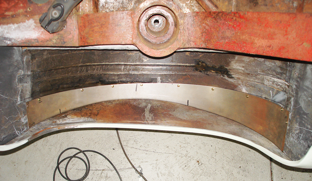
The filler piece screwed in place to check the fit and contour to match the outer guard.
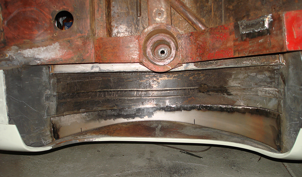
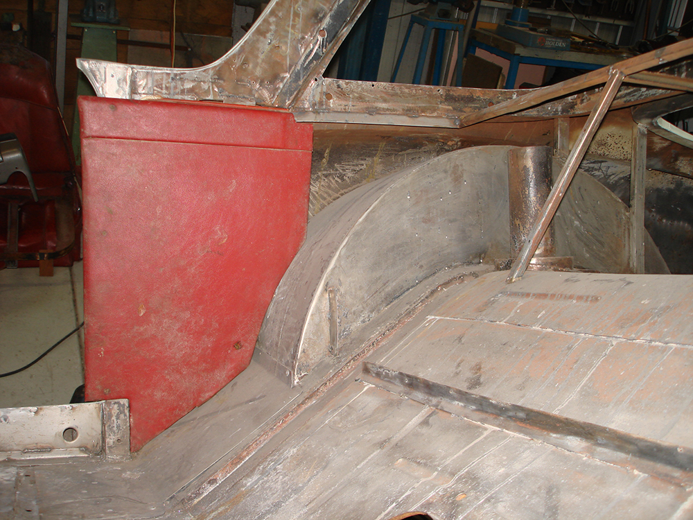
The completed iner guard filler welded in place. Note the plate welded to the chassis rail with 2 holes is for addition of a rear sway bar to control the free movement of the diff now there will be no torque tube stabilizer, which I think helped to control body roll. There is a small gap between the filler piece and the guard which will be filled with an industrial sealer after painting. While the overlapping filler may look a little strange it is the same method that was used originally and I have eliminated one overlapping piece.
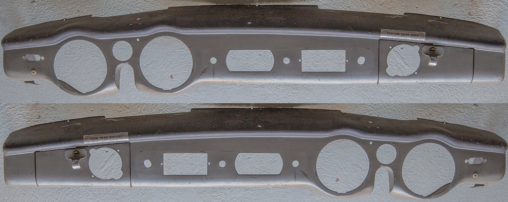
I now need to modify the dashboard to right hand drive, the image above is photo reverse yo give me a guide, if only it was that easy!
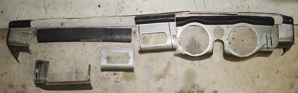
The dash cut into sections after careful measurement as a start to the modification.
Page 14
Home